This author's experience with analog audio circuit design extends over a period of 50 years -- the era of the vacuum tube, long playing records, FM radio, tape recording, and transistors. It also includes the digital era where computers became involved with audio. Since the subject of this paper is analog audio, digital audio signal processing is not discussed.
2) Historical Background
In his youth, the author was fortunate in growing up and being educated in a geographical region, east coast U.S.A., Philadelphia, New York, Boston, M.I.T. - Harvard; during a time extending from the 1940's to the late 70's. In 1954, I met David Hafler and Irving Fried, who lived near my family home in Philadelphia. Through their association and friendship I met a number of the east coast audio figures of the time. At that time David Hafler and Herb Keros were manufacturing ACROSOUND transformers for the Williamson amplifier. Later on, Hafler went on to form Dyna Company, manufacturing audio output transformers, amplifier and pre-amplifier kits, Dynakits.
As Chief Engineer in the early vacuum tube days with Dynaco, I met and spoke with other audio designers, i.e. Stuart Hegeman, Ben Drisko, Frank McIntosh, and Henry Kloss. Out of these meetings a philosophy of design was emerging which encompassed the whole audio reproduction process. As time went on I became acquainted with Emory Cook, Rudy Bozak, Paul Weathers, Edgar Vilchur, Arthur Janszen, and Donald Chave (LOWTHER, U.K.).
Although my primary interest developed in the basic physical sciences, my interest in music and sound reproduction has persisted to this day. Over a period of decades, experience and introspection have resulted in the evolution of certain precepts which comprise the Method of DePalma in analog audio circuit design. The philosophy and working out of these ideas are exemplified in the three power amplifier designs presented here.
3) Philosophy
Analog circuit design I would characterise as an Art. Digital circuit design I would characterise as a geometry. Art is said to be in the eye of the beholder, consequently it is not altogether a logic process which governs the choice of a circuit topology. The object of our desire is a pleasing and satisfying musical experience comparable on some basis with the original performance. Over the history of evolution of the artificial -- and now electro-mechanical reproduction of sound, certain notions more commonly associated with the music being reproduced injected themselves into the specification of electrical parameters.
The ideas of stability, linearity, harmony, balance, and power express themselves in electronic circuitry. Imagery developed; it could be conceived the analog audio power amplifier expressed itself out of the properties of the reproduced music. Out of the amplifier configurations and possibilities assembleable through the known (fixed) laws of electricity and the properties of the known active amplifier devices, of these which are the musically acceptable topologies?
It is postulated here that the musically acceptable topologies must necessarily satisfy all the electrical laws as well as the musical ones. Conformity with musical laws converts an experiment in electromechanically induced transduction into a musical experience.
4) Tubes and Transistors
Amplifiers designed using active devices, i.e. tubes and transistors, are similar in conception to modern multi-element high-speed photographic lenses. In lens design, materials with definitely non-linear properties, chromatic and spherical aberrations, are balanced off against each other to result in a magnification (gain) without chromatic aberration (flat frequency response). High signal to noise and reduced intermodulation, (modern low reflection lens coatings). The exceptional quality of modern optics speaks to the achievement of this balancing. In fact the resolution of a modern (diffraction limited) lens is regulated by the properties of the light passing through it. This principle carries over into electronics where gain and linearity can be achieved by balancing the inherent curvatures of active devices. A push-pull class A transformer coupled circuit demonstrates this. There is probably no inherent musical superiority of tubes vs transistors. All known gain - transconductance devices have separate and individual characteristics. The design problem is to interface the active elements with the circuit topology in the most harmonious manner.
Ninety years of development of vacuum tube circuitry during the analog era have probably resulted in better Hi-Fi than 50 years of transistor circuitry developed during a time when analog techniques are on the decline and digital technology is on the ascendency.
5) The First Circuit
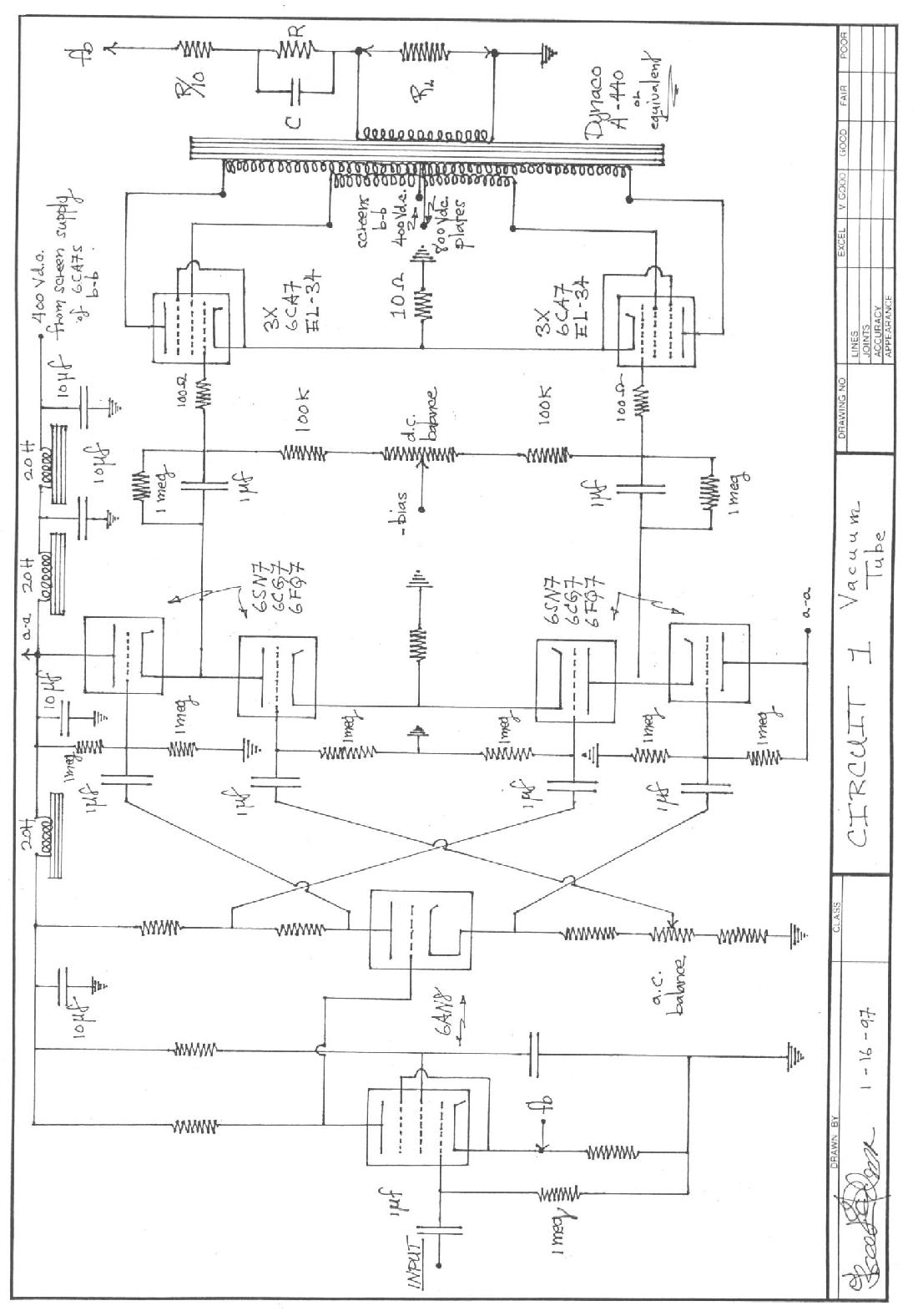
The first circuit is the oldest, making use of a.c. coupling, vacuum tube active elements, transformer coupled push-pull Ultralinear output. Having stewed in the ferment of 50's golden age audio, it is a combination of tried and true with a distillation of the ideas of D.T.N. Williamson and Norman Crowhurst.
The driver circuitry is the input pentode direct coupled to a triode split load phase inverter. The pentode section, (6AN8), operates at a low plate voltage making for satisfactory direct coupling to the phase inverter grid. Low frequency gain and phase shift is controlled by the size of the screen bypass capacitor.
It is well known that even though signal current is common to both the cathode and plate load resistor of the split load phase inverter, because of the differing incremental impedances at the cathode and plate the circuit can become unbalanced at high audio frequencies. A circuit has been devised, figure (1), to provide low impedance drive to the output tubes as well as correct the high-frequency unbalance of the phase inverter. In this circuit the voltage output is controlled through the upper (cathode follower) grids and the current in the load by the drive to the lower tubes' grids.
With the combination as shown using a 6AN8 inverter driver and two 6SN7s, 6CG7s, or 6FQ7s, the frequency response is identical for both sides, minus 3db @ 35kc.
Driver output impedance is 600 ohms. The fraction of the plate or cathode load resistor of the inverter stage tapped off to drive the lower tubes' grids is determined by experiment. The drive to one of the lower tube's grids is adjusted for a.c. balance or lowest distortion.
Coupling to the output tubes' grids is via a "step network" which gives zero phase shift at d.c. This is important for stability. Output is push-pull Ultralinear with a tertiary winding for differing plate and screen voltages. Negative fixed grid bias voltage is supplied to the output tubes by a separate d.c. power supply.
The output cathodes are tied to ground through a 10 ohm wire-wound common cathode resistor. The size of this resistor regulates output stage distortion at high levels. Distortion at high levels is reduced at the expense of a small increase in low level I.M. The 10 ohm value represents a compromise.
It is essential for Hi-Fi use that the voltages applied to the circuit build up gradually. Voltage surges can cause flashovers in the output tubes which could damage delicate loudspeakers.
The all vacuum tube first circuit requires a rather elaborate power supply. At full output, 250-300 watts, it must be able to maintain the output tube plates at 800 volts and the screens at 400 v.d.c. The low level stages and the driver circuit are isolated via L-C filtering from the output tube plate circuit.
With single ended stages in the input driving a class AB output stage unwanted feedback through the power supply sicklies over the audio image.
It goes without saying that d.c. delivered to all amplifier stages must be pure d.c. without ripple. Under certain conditions the effects of power supply ripple under load may be ameliorated by complementary (transistor) circuitry. On the other hand there is no substitute for pure d.c.
For circuit one the power transformer provides 800 v.a.c. center tapped to a full wave bridge rectifier composed of four 6AU4 damper diodes. Under light load, quiescent conditions for the amplifier, this circuit gives one-thousand volts for the plates of the output EL34s. The transformer center tap gives 1/2 voltage, i.e. 500 volts d.c. for the screens.
Individual filtering of the plate and screen busses is by two stages each of pi section 15 henry chokes with 10 microfarad paper filtering capacitors, except for the input capacitor which is 5 microfarads. The 500 volt buss is further filtered by two more pi sections using 20 henry chokes and 10 microfarad paper capacitors. This line feeds the driver section of the circuit. The B+ for the input 6AN8 triode-pentode is further isolated with another pi section using a 20 henry choke and a 10 microfarad filter capacitor.
Output tube negative grid bias is supplied from a separate half wave silicon diode rectifier working into a single pi section filter using a 20 henry choke and 100 microfarad low-voltage electrolytics.
The 6AU4 damper diodes have good enough heater cathode insulation so that they may be operated from a common 6.3 v.a.c. winding. The slow warm-up of the heavy duty filaments applies the high voltage to the circuit with a smoothly rising voltage build-up. A separate 6.3 v.a.c. winding supplies the filaments of the power amp.
Use of high-voltage paper filter capacitors gives essentially unlimited lifespan as compared to electrolytics which are good for about 20 years when operated within ratings. Use of paper capacitors will ensure a constant, low power supply internal impedance over the audio range.
The power supply should provide two functions. Firstly to supply steady d.c. to all stages, and secondly to isolate the stages in such a way that unwanted feedback loops are not set up between them. This is especially important with single ended low level stages. Because of complementarity, transistor stages can be balanced to eliminate common mode (power supply) fluctuations from the output. Tubes come in one sex only so that the balancing operation is much more difficult, leading to the use of differential circuitry which has its own complications.
It is hard to make general statements about power supplies for audio amplifiers. Even with perfect balance, intermodulation can result if a gain parameter is sensitive to current. The pentode-like characteristics of solid-state devices make them less sensitive to power supply voltage fluctuations than triode vacuum tubes.
Suffice it to say that power supply configuration and topology is just as important as amplifier design. If there is complementarity in vacuum tube circuit design it is expressed in the relationship of the active circuit to its power supply. It is in this that the musical as well as the electrical laws are satisfied.
In the circuit described 20db of negative feedback is taken from the output transformer secondary 8 ohm tap to the cathode of the input pentode. The circuit is set up by adjustment of the feedback resistor bypass capacitor to produce a critically damped 20kc square wave into an 8 ohm non-inductive load. The feedback network is a step circuit to prevent excessive high-frequency feedback in a range where internal amplifier and transformer phase shifts could produce oscillation, especially with capacitor (electrostatic loudspeaker) loading.
With all other low-frequency time constants as indicated a low-frequency 2 c.p.s. d.c. function generator is used for the adjustment of the screen bypass of the input pentode. Perfect reproduction of the low-frequency square wave is what is desired. In this circuit with 20db of overall negative feedback this capacitor should be adjusted to reproduce the 2 c.p.s. square wave at the output without slope or tilt. Too large a screen bypass capacitor will produce overshoot, indicating an undesirable peak in low-frequency response. These tests must be done at a low signal level into an 8 ohm load to avoid saturation of the core of the output transformer.
In some respects circuit one is derived from the earlier (1948) Williamson amplifier design. The Williamson amplifier could exhibit a constant low-frequency oscillation resulting in a "breathing" action of woofer cones moving in and out, triggered by wow or rumble in the reproduction of long-play vinyl discs.
The Williamson amplifier was stabilised by the use of "step" network coupling of the driver plates to the output tube grids. This modification corrected the low-frequency phase response and was originated by Norman Crowhurst.
Circuit one incorporates step circuit coupling to the output tube grids as well as the low-frequency phase and gain adjustment afforded by variation of the screen bypass capacitor of the input pentode.
In a vacuum tube amplifier there is essentially zero time delay between the signal grid drive and a current response at the plate. This not the case with transistors where the flow of charge carriers through solid semi-conductors is much slower than electrons moving through a vacuum.
The limitation in the use of negative feedback to reduce distortion occurs because of phase shifts in the circuit elements adding up to 180 degrees at subsonic and ultrasonic frequencies and thus turning negative feedback into positive feedback. This is especially true when an output transformer is one of the circuit elements. Experience has shown that 20db of feedback is optimum in a circuit where it takes 30 - 35db to make the circuit oscillate. Negative feedback is very useful in distortion reduction if not overdone.
DePalma likes to design his circuits so that there is only one voltage gain stage, i.e. the input pentode. The subsequent stages are unity gain cathode followers.
Listening tests by this author have determined that different power output tube types have different sounds. Different brands of the same tube also sound different. The two generic tube types are the beam tetrode and the pentode exemplified by the KT-66 and the EL-34/6CA7. The KT-66 has a sweet, smooth sound, and the EL-34 a sound which has been characterised as dry. I do not prefer the sound of the 6L6, 6550 or KT-88. I think the EL-34 pentode originally manufactured by Philips and later by U.K. Mullard, and German Telefunken, is the best audio tube ever made. For what it's worth, I listen to a stereo system with one channel EL-34s and the other KT-66s.
Vacuum tubes have long reliable lifespans when operated within ratings, and especially at high voltages and low currents. The fastest way to shorten power tube life is to over-dissipate the tubes.
There was a time in the history of audio power amplifier design when output tubes were run at excessively high currents to achieve low I.M. distortion. This led to short tube life necessitating replacement every six months or so of continuous listening to maintain specs.
A trend developed of operating plates and screens at the same voltage. At the same time, amplifier manufacturers tried to maximise output power, necessary because of the extremely low acoustical efficiency of acoustic-suspension, AR, KLH, and electrostatic type loudspeakers. Operation of plates and screens at the same voltages, obtained from Ultralinear tappings on the audio output transformer primary, leads to a dangerously unstable situation as plates and screens are taken up to the 500 volt level. Excessive electron current can cause the screen wires to become incandescent, increasing tube current to destruction. The screens of EL-34s should be in the "shade" of the control grid wires. Later versions of EL-34s manufactured in the 80's and 90's may not be as carefully assembled as the original Philips construction.
The best way to get high power and low distortion is to operate EL-34s at high voltage. The EL-34 can give 100 watts/pair with 800 volts on the plates and 400 on the screens. This necessitates a tertiary screen winding on the output transformer. The best transformer for this purpose is the Dynaco A-440, or one of its clones. At the 800-400 plate - screen voltage ratio this transformer can give 300 watts output between 30 cycles and 15kc, 200 watts 20-20kc.
In the amplifier design described no load voltages on the output tube plates and screens are 1000, 500 respectively. Over the 40 years of experience I have had with this design no special problems have developed with the exception that these voltages should be applied with a controlled build-up which is obtainable from the vacuum tube damper diode rectifiers which are employed. Tubes also flash occasionally from loose internal particles. A few sharp raps generally loosens them.
DePalma and Hafler discovered the distortion reducing properties of a small common cathode resistor in class AB circuits when they were looking for an easy way for the customer to set the output stage bias. A 12 ohm resistor equated to a 1.56 v.d.c. drop which was equal to the voltage of a 1.5 volt dry, zinc-carbon cell. It also turned out that this resistor reduced high level I.M. by 2/3, down to .25 percent, while low level, one-watt I.M. was only perceptibly increased.
Use of a 10-12 ohm common cathode resistor in class AB push-pull audio power output stages allows a reduction in quiescent static current to achieve the same distortion at maximum output. Any reduction in tube current will increase tube life. A small common cathode resistor together with high-voltage, 800-400, operation of the EL-34 can result in a tube life in excess of 20 years.
The important parameter in vacuum tube life is bulb temperature. Output tube temperatures high enough to burn fingers when touching the bulb evaporate getters on the inside of the envelope. These tubes eventually become gassy and lose emission. Anyone serious about vacuum tube amplifier design must either contemplate manufacturing his own tubes or developing circuits which maximise the performance and life of the existing remaining stocks.
In the early days of Hi-Fi the earth had not reached its limit of planetary resources. Economic considerations had not yet reached a limit where price and "performance" were intra-convertible or even relevant. The important fact was to achieve musical performance for one's Hi-Fi system. The contemporary aphorism is not whether it is musical but good value for the money. As we drift into our uncertain future we have lost touch with music.
6) The Second Circuit
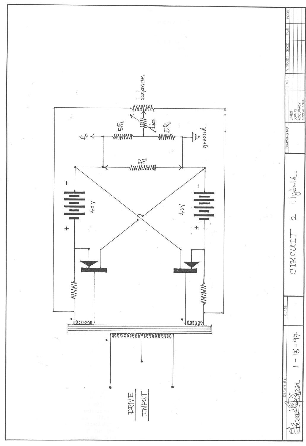
The second circuit was developed as a hybrid tube-transistor audio power amplifier. In the original design a DynaKit 6AN8 voltage amplifier phase splitter drove a 6360 single envelope twin tetrode, Ultralinear connected. The output transformer was a Dynaco A-410 modified with normally paralleled 16 ohm secondaries separated. These windings drove one or more pairs of same sex transistors in the manner shown, figure (2).
A single power transformer with two capacitively isolated 40 volt windings and a 250 volt winding for the two tube phase inverter driver was used. The 6360 power stage need only put out a few watts to drive the transistors to saturation. In the circuit constructed a bypassed common cathode resistor provided bias.
The second circuit can also be driven by a transistorised voltage-amp-phase-inverter-driver. The salient features of this output circuit are that identical same sex transistors can be used and because of the floating nature of the transformer coupled drive, either end of the output load resistor may be grounded. Negative feedback to the input stage cathode (6AN8) is taken from the ungrounded end. Either same sex bipolars or FETs can be used in this circuit.
Vacuum tubes come in only one gender. Transistors can be N type or P type. An N type transistor can be synthesised from a P type and vice-versa, by what is known as a quasi-complementary circuit. Quasi-complementary circuits using combinations of N and P type transistors work well but direct fabrication of fairly well matched N and P type complementary power transistor pairs has put these circuits on the back burner.
Of course a purist designing class B transistorised audio power circuitry would never consider using complementary pairs, being that the matching is not perfect. On the other hand this necessitates the use of an audio driver transformer, the imperfections of which limit the amount of overall usable negative feedback.
The reason I consider the transformer coupled driver circuit acceptable is that exact matching of the output power transistors is possible. This in itself minimises even order harmonic distortion. Small low-power, 10 watts or less, driver transformers have excellent frequency response extending to 100kc for the A-410. Capacitive effects between windings and their attendant resonances in a small transformer are well outside the audio range.
Larger and bigger audio output transformers normally used in the range 100 - 500 watts have definite high-frequency resonance and leakage problems which limit the overall amount of negative feedback which can be used. For example, the 250 watt output of the first circuit can be obtained at about .5% I.M. using 20db of negative feedback. Oscillation would occur at 32db feedback. In the second circuit 100 watts could be obtained from a pair of diffused-base bipolars @ .25% I.M. In this design 25db of feedback could be used with oscillation occurring at 35db.
Because of stored base charge and propagation delay effects, negative feedback is not as effective in distortion reduction for transistorised power amplifiers as for tube-transformer designs. In the same vein, excessive negative feedback may create non-harmonious distortion in transistor circuits. Consequently whatever the design, the principle should be to obtain the lowest distortion before feedback is applied. Negative feedback as a cure for distortion when properly applied can have non-harmonious and destructive (oscillatory) side effects if overused.
I like the second circuit because it can employ same sex matched and balanced transistor pairs to achieve any desired output power. Even though a small low-power driver transformer is required, the problems it solves more than compensate for the few ills a well designed and constructed audio transformer produces.
As is well known, the vanishingly small distortions which can be obtained in fully transistorised audio power amps are not necessarily reflected in their audio listening quality.
7) The Third Circuit
The third circuit was developed to fully utilise complementary symmetry matched P and N type field-effect transistors. Using these devices, a fully d.c. coupled audio power amp was designed. In recent years audio quality has been adversely affected by the use of plastic dielectric coupling capacitors. There are well known memory and electric hysteresis effects in plastic dielectrics. If coupling capacitors are used in audio circuits they should be paper or metalised paper dielectric. Of course, d.c. coupling removes all capacitors as shown in the third circuit, figure (3).
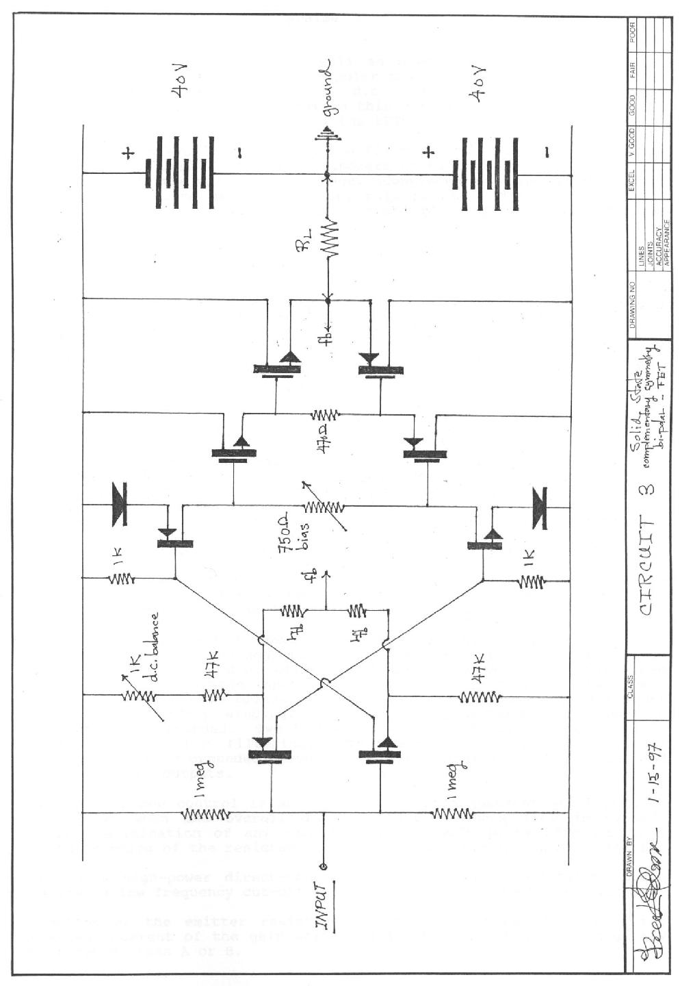
In this circuit the musical as well as electrical laws are followed. Complementary symmetry, FETs and bipolar transistors are all utilised in a completely balanced, symmetric, d.c. coupled configuration. The experienced designer will see that in this circuit complementary symmetry bipolars can be substituted for all the FETs.
In order to achieve d.c. coupling the first stage of this circuit has a voltage gain of less than unity. Bipolars or FETs may be used here. The second stage is the voltage gain stage. Complementary bipolars should be used here to insure maximum voltage, rail to rail, drive. The second stage is interesting because it is a combination of two driven current sources using each other as load resistor.
The diodes in the emitter circuit are used in a dual mode. Using complementary bipolars as recommended, these diodes provide temperature compensation in conjunction with the 1K base to ground resistors. The other function is to ensure the lowest base input resistance in the voltage amplifier stages. The current supplied to the gain stages by the input transistor pair divides between the base to ground resistor and the input resistance of the gain stage, i.e. the lower the base input resistance the more driver current flows into the gain stage transistors.
If the base input resistance were zero, all the driver current would flow into the bases and the gain of the two-stage combination would be highest. Substitution of complementary FETs in the gain stage changes the input situation since FETs are voltage actuated.
In the gain stage each transistor acts as the load resistor for the other. Very high gain and linearity is possible. Using bipolars, the drive output of this stage is almost peak to peak, rail to rail, less the saturation voltages and emitter diode voltage drops. The gain of this stage using bipolars is 1000-1500. Since the second stage operates as a current source a variable series resistor in the common collector circuit can be used to regulate the output stage quiescent current. As can be appreciated from the circuit schematic, any supply voltage variations either from mains fluctuations or long term thermal temperature co-efficient effects in the active devices appear only as a common mode effect and do not shift the d.c. balance point of the circuit.
Circuit three requires a power supply with exactly equal and opposite output voltages balanced against ground. This ensures, all other things being equal, that no d.c. offset will appear across the output load resistor for zero voltage input to the amplifier. A proper circuit uses a four diode full-wave bridge rectifier fed from a center-tapped power transformer secondary winding. The center-tap becomes a 1/2 voltage point which is grounded. Two 1000 microfarad electrolytics connected in series are used for filtering. The center point of the seriesed capacitors is also grounded, providing adequate filtering of the plus and minus 40 v.d.c. outputs.
The d.c. balance control is an internal set-up adjustment which becomes ineffective when the overall d.c. negative feedback loop is closed. Complete elimination of any remaining offset voltage is effected by a minute trimming of the resistance of one of the 1 megohm input resistors.
(Use of a high-power direct-coupled amplifier for high-fidelity audio requires a low frequency cut-off to prevent damage to loudspeakers.)
Selection of the emitter resistors of the input stage determines the quiescent current of the gain stage. Interestingly, the gain stage may be operated class A or B.
The emitter-follower following the gain stage can be either bipolars or FETs. An important parameter here is the input capacity of these devices which can cause a high-frequency roll-off. This roll-off can be used as high-frequency phase compensation. When using FETs, their extended frequency response can lead to R.F. oscillations. This can be controlled by series "stopper" resistors of up to a few hundred ohms in the gate circuits.
With FETs in the input stage and bipolars in the gain stage, negative and positive temperature coefficients work against each other. If quiescent output stage current is temperature sensitive in the sense that d.c. compensation of the input stages does not offer complete control, then a series diode string between the output driver transistor bases (or gates) can replace the resistor control shown between the driver transistor emitters.
The third circuit can drive several pairs of paralleled output transistors. A complementary symmetry FET emitter-follower drives the output transistors. The emitter-follower driver fed from the driven current source gain stage provides low distortion symmetrical rail to rail drive to the output stage. Here again complementary bipolars can be substituted for the FETs.
The output stage can be either bipolar or FET. An alternative method of regulating quiescent current is a series diode string in the emitter circuits of the driver stage. This might be more important with a bipolar output stage since temperature compensation with negative co-efficient diodes is possible. The built-in negative temperature co-efficient of current in FETs renders this unnecessary. As a strictly purist comment, I do not like to use diodes in a signal path. They may be forward biased and in conduction, but they still have a non-linear current-voltage relationship as compared to a resistor.
Negative feedback in the third circuit is from the hot end of the load resistor (loudspeaker) to the input emitters. To obtain best square wave response and transient stability this resistor may be bypassed by a small capacitor. If the feedback resistor is connected between the two points marked fb and bypassed with a small capacitor, the identical emitter resistors in the input stage can be adjusted to be some fraction of the main feedback resistor. Thus a "step" network is created which limits feedback at high frequencies and improves stability. Experiments with this circuit showed that oscillation ensued with 55db of feedback.
The designer should produce a circuit which has inherently low distortion before feedback is applied. Odd harmonic distortion can be balanced out by symmetry. Even harmonic distortion is reduced by choice of inherently linear circuitry, i.e. emitter-follower output and output driver circuits, and a linear driven current source symmetrical high-gain stage.
With the above combination distortion does not continue to decrease above 30db of feedback. Just under clipping and at full output into 8 ohms, I.M. distortion of the third circuit is unmeasurable or in the noise level of the instrument. Power response is flat from d.c. to 100kc where the output is rolled off deliberately through internal compensation. One-half volt d.c. input drives the amplifier to full output. At 30db of negative feedback no compensating capacitor was required across the feedback resistor to produce a perfect 20kc square wave.
The third circuit was designed to take advantage of the most advanced semi-conductor technology available today (1990's). I have felt that transistor audio power amplifiers could equal or out-perform the best vacuum tube designs. Analog audio thrived in the days of vacuum tubes, but design has turned away from analog to digital and the serious evolution of analog transistor power amplification has never taken place.
Transistors have made it possible to eliminate the audio power output transformer from audio amplifiers. Complementary transistors make new design options possible. The pentode-like high incremental impedance of transistor collector circuits reduces filtering requirements of power supplies. Total d.c. coupling is possible in complementary circuits thereby eliminating all coupling capacitors.
I like the sound of all three circuits, but the third circuit represents all I know about electrical and musical laws. The sound is sweet, smooth, effortless and transparent. 100 watts of audio can be gotten from 8 transistors and 6 diodes. The history of the development of electronic audio rests on the control of the flow of current, firstly via the vacuum tube grid, then by carrier injection into a back biased semi-conductor junction, finally control of transconductance via an electric field projected into a semi-conductor. Other means of current control may be possible and some might be practicable.
Returning to the golden rules of audio, the simplest design with the fewest stages is preferable and if balance, complementarity, linearity and power are the musical factors I would prefer circuit 3.
The reproduction of music electro-mechanically does not lend itself to the manipulations of the digital computer and the exigencies of apparently "perfect" analog to digital and digital to analog conversion.
Offshoots of contemporary inattention to perfection are the operational and differential amplifier circuit chips. Analog design has been relegated to the ministrations of specialists who design large scale integrated circuit chips. Amplifiers are not designed but specified. Differential amplifiers are installed as input circuits where negative feedback is not applied to the same active device as the signal. This tactic, often haled as a great freedom in the design of amps with "balanced" negative feedback, builds in irreducible distortion from a stage of amplification not includable in the negative feedback loop.
The degree of perfection and subtlety of design required for Hi-Fi analog audio mandates discrete design of audio circuits and the avoidance of prepackaged integrated circuits with their attendant "commercial" mass-produced sound.
Negative feedback must be applied in a single loop from the output load terminal to an input device. The signal and feedback must interact in the same active device. Those who care to study the subject of feedback further should read: Valley and Wallman, Vacuum Tube Amplifiers, M.I.T. Rad-Lab Series. Further wisdom on the subject of negative feedback can be gotten from the works of Norman Crowhurst.
This paper has been written for professionals in the field of active analog audio circuit design. It is not intended as a "how-to" construction article. Writing a design paper is different than a scientific article. Design is the selection of an appropriately chosen set of concepts to motivate and actualise a particular function, i.e. electro-mechanical analog audio sound reproduction.
What has been sketched out in this paper are the sets of concepts and choices DePalma would, and has, made in his pursuit of an audio image expressed electronically. Other sets of choices are available and can be woven into a rationally acceptable audio image. The choice is in the eye of the beholder and in the ear of the listener.
Bruce DePalma